Safety Connectors and Wiring
In this section the safety connectors are described and their proper wiring is shown.
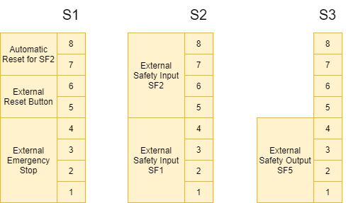
Safety Connectors
The safety connectors S1, S2 and S3 are placed on the upper side of the control unit under the protective cover.
| Connector Pin | Description |
| Connector S1: Basic functions | |
| 1 | Emergency Stop 1-out |
| 2 | Emergency Stop 1-in |
| 3 | Emergency Stop 2-out |
| 4 | Emergency Stop 2-in |
| 5 | 24 V |
| 6 | external reset in |
| 7 | 24 V |
| 8 | automatic reset SF2 in |
| Connector S2: Safety Inputs | |
| 1 | 24 V |
| 2 | SF1 input-1 |
| 3 | 24 V |
| 4 | SF1 input-2 |
| 5 | 24 V |
| 6 | SF2 input-1 |
| 7 | 24 V |
| 8 | SF2 input-2 |
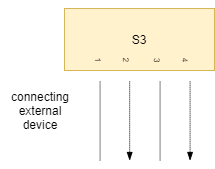
| Connector S3: Safety Output | |
| 1 | GND |
| 2 | SF5 output-1 |
| 3 | GND |
| 4 | SF5 output-2 |
| 5 | – |
| 6 | – |
| 7 | – |
| 8 | – |
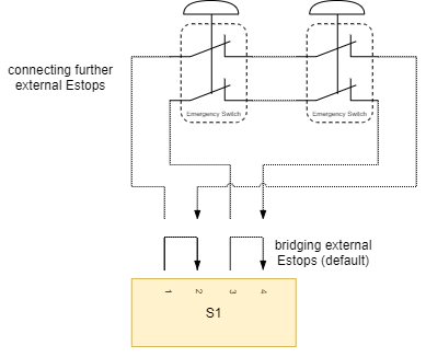
Wiring the External Emergency Stop Switch (SF0)
The following figures show the correct wiring of the safety connectors.
Connecting an external emergency stop
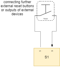
Connecting an external reset button
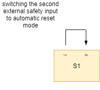
Enabling the automatic reset mode of the second external safety input (SF2)
Connecting an external safety device/senso (SF1)

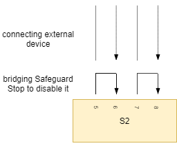
Connecting another external safety device/sensor (SF2)
Connecting an external safety device to the robot stop output (SF5)