General Setup
Note
Section under construction.
This section provides an overview of the modular robot system.
Components
Components required for operating the modular robot system:
- Modular robot with base (Module Assembly).
- Control unit.
- Enabling device with E-Stop.
Modular Robot
Assembled modular robot as described in Module Assembly.
- Pic.
Connectors and Ports at the robot base
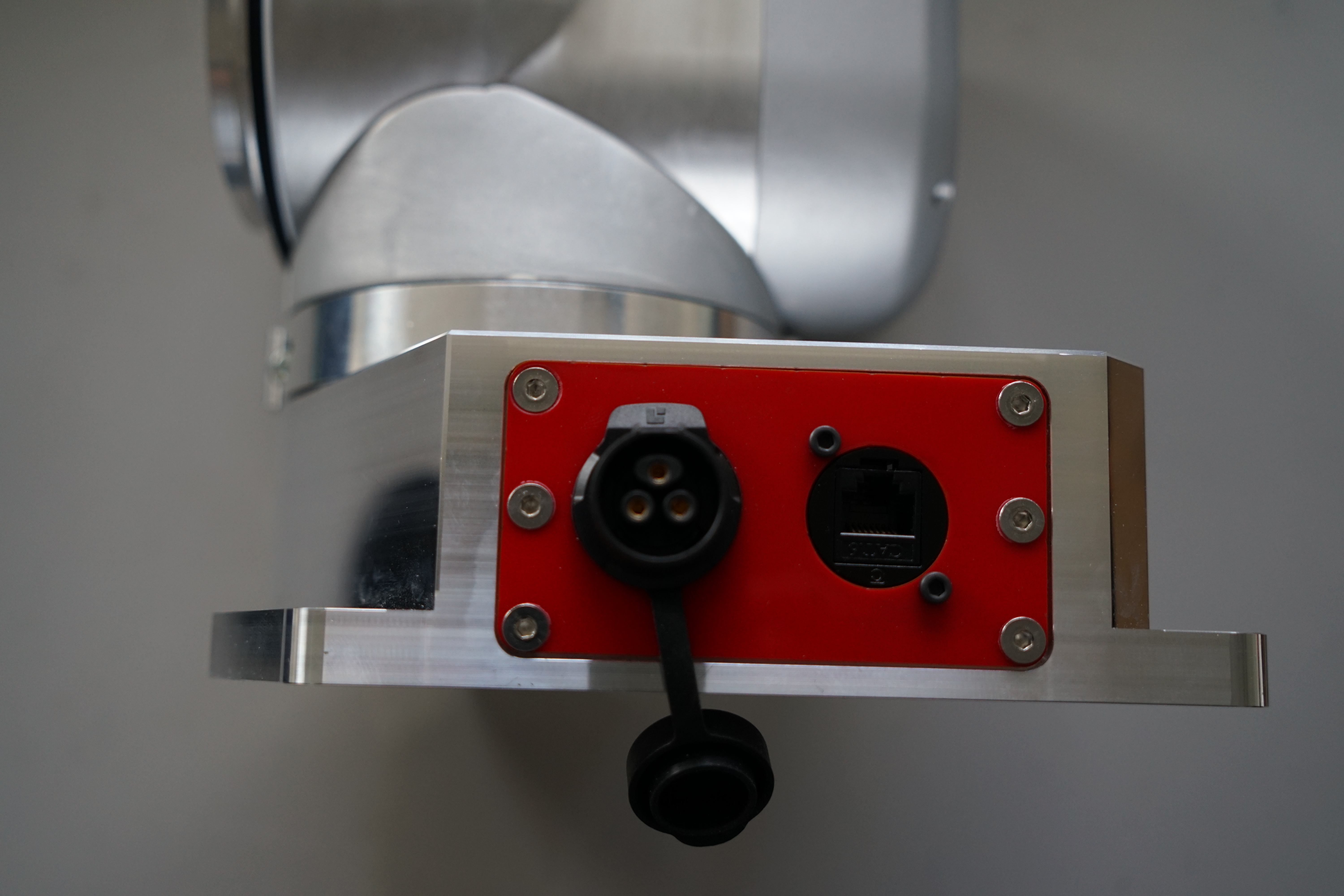
Connectors at the robot base: Left: Power. Right: Communication.
Control Unit
Robot control unit including the power supply.
- Pic.
Connectors and Ports at the control unit
Version 0.1
Version 0.2
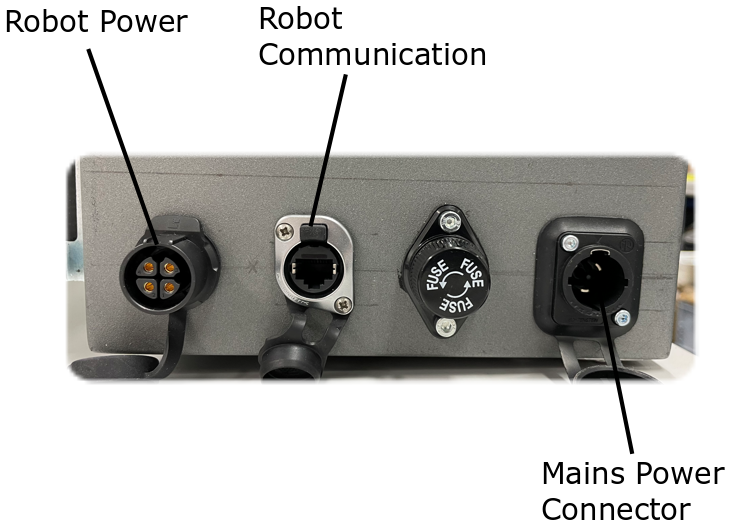
Connectors and ports at the side of the control unit.
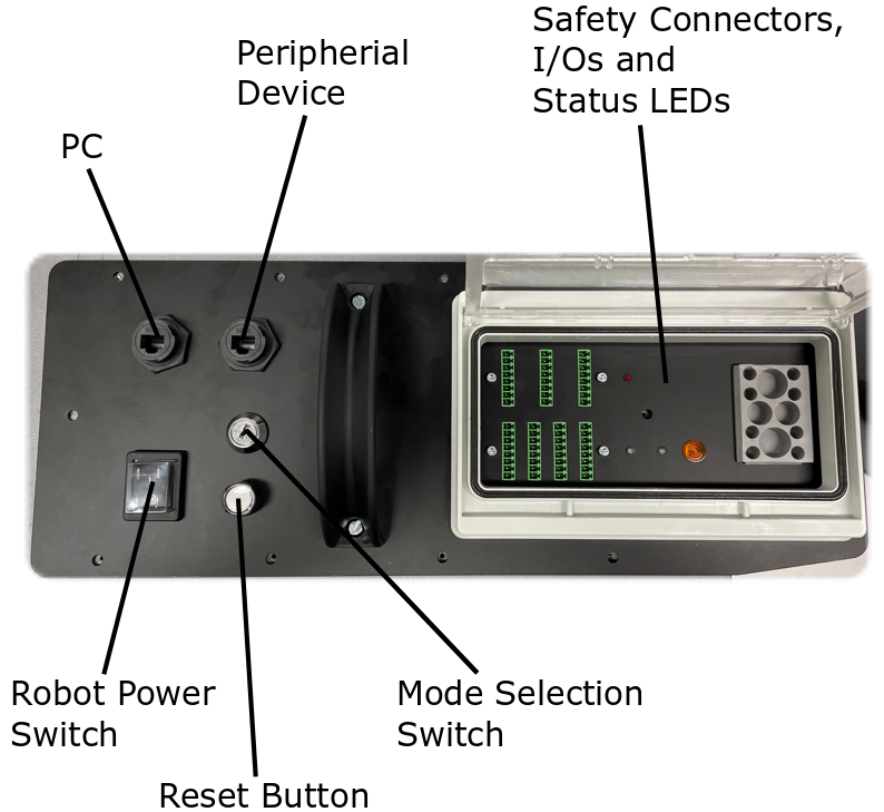
Connectors, ports and switches on the top panel of the control unit.
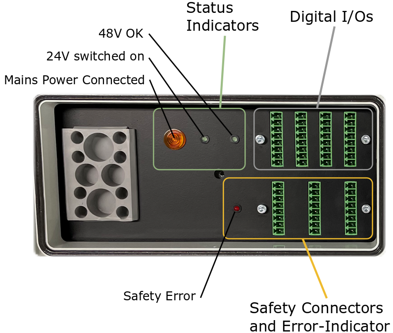
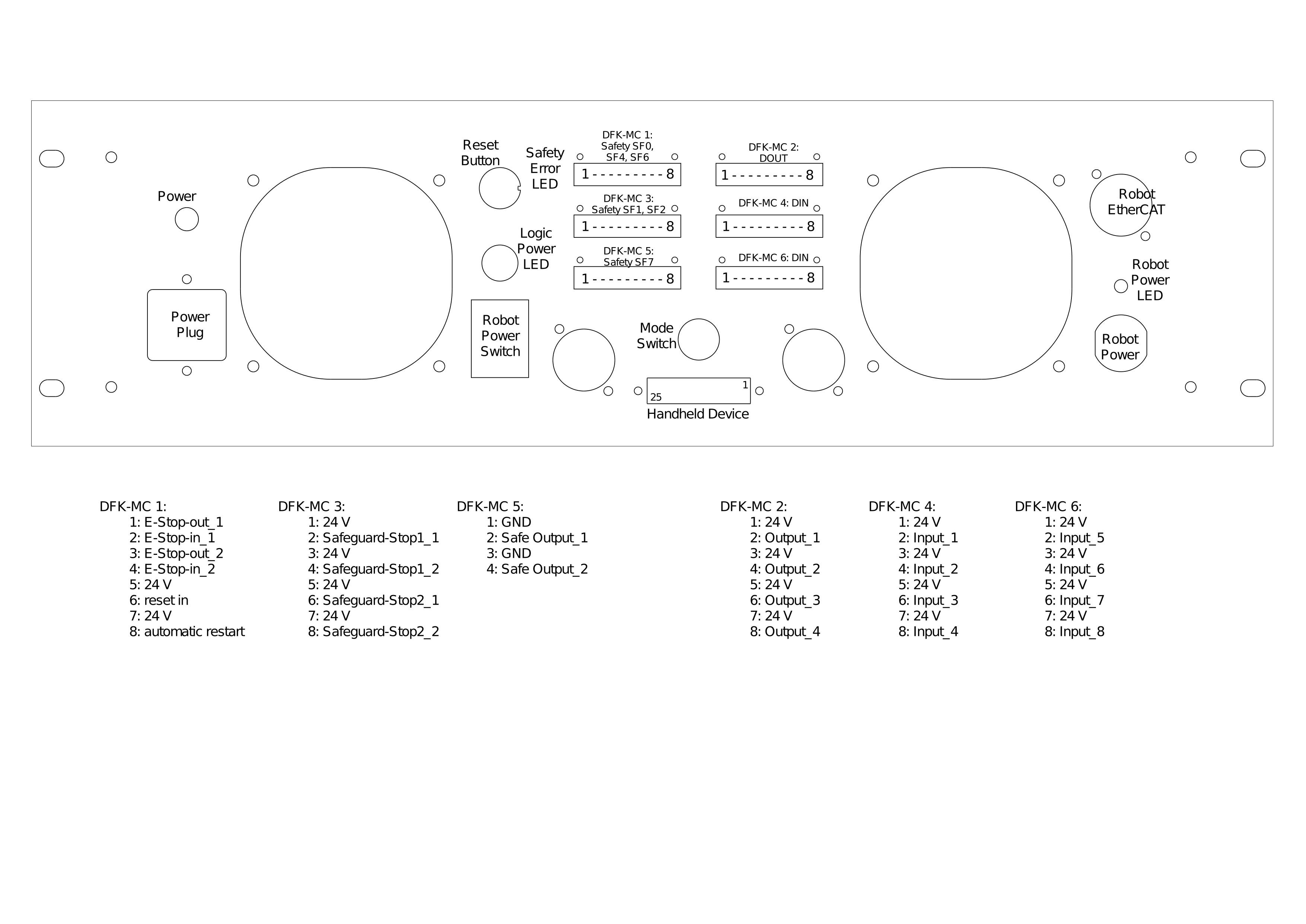
I/O-connectors, safety connectors and status indicators on the top panel of the control unit.
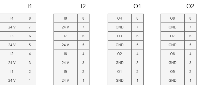
Schematic of I/O-connectors.
Connecting the Robot to the Control Unit
- Connect Robot Power to the power port located at the robot base. Make sure that Robot Power Switch is in the Off position before connectiong or disconnecting the robot power cable.
- Connect Robot Communication to the commuication port at the robot base. Make sure that the emergency-stop button is pressed before connecting.
The connectors for
Enabling Device
To operate the robot, a hand-held enabling device needs to be connected to the control unit. This enabling device is equiped with a 3-position switch that has to be held in the mid-position by the operator while operationg the robot in manual mode.
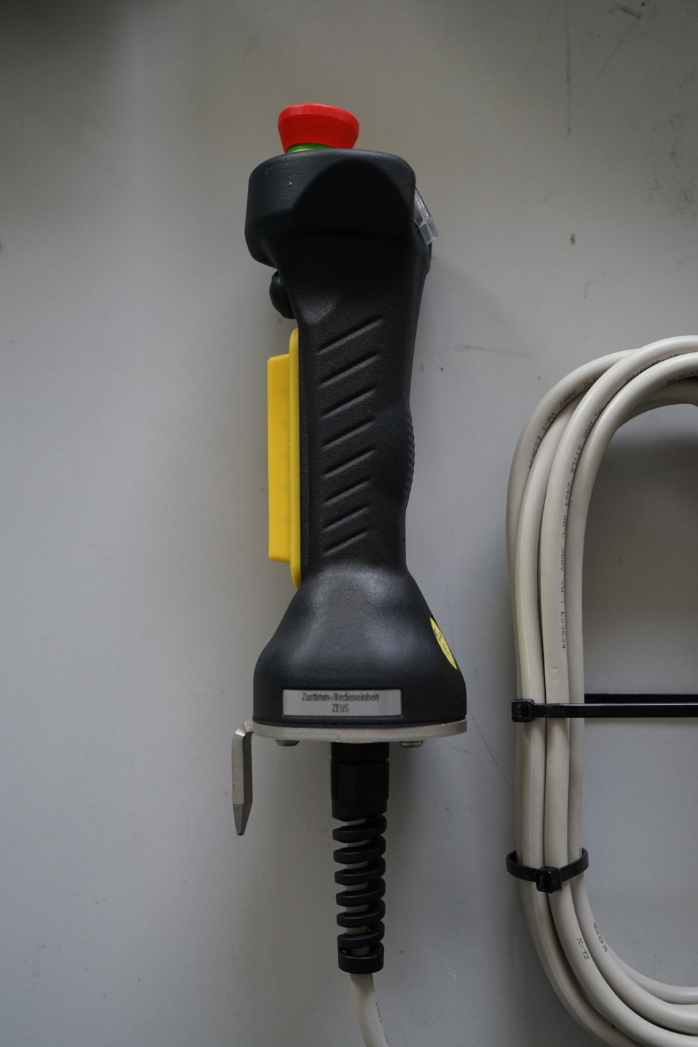
Enabling device equipped with a 3-position switch (yellow, only active in manual mode) and an emergency-stop button (red, always active).
Module Assembly
This section provides information on how to assemble a robot from individual modules.